Practical Strategies for PCB Assembly Cost Reduction: Real Examples from the Field
Practical Strategies for PCB Assembly Cost Reduction body { font-family: Arial, sans-serif; line-height: 1.6; margin: 20px; } h2 { color: #2c3e50; } table { border-collapse: collapse; width: 100%; mar...
Introduction
In the fast-paced world of electronics, reducing the cost of PCB assembly while maintaining quality is a critical challenge. As consumer demand grows, the pressure on manufacturers to deliver efficient and cost-effective solutions also increases. This article explores practical strategies for reducing PCB assembly costs, focusing on component specifications, selection criteria, and application circuits. Drawing from real-world examples, we delve into the intricacies of PCB design and assembly, providing actionable insights for engineers and manufacturers alike.
Technical Overview
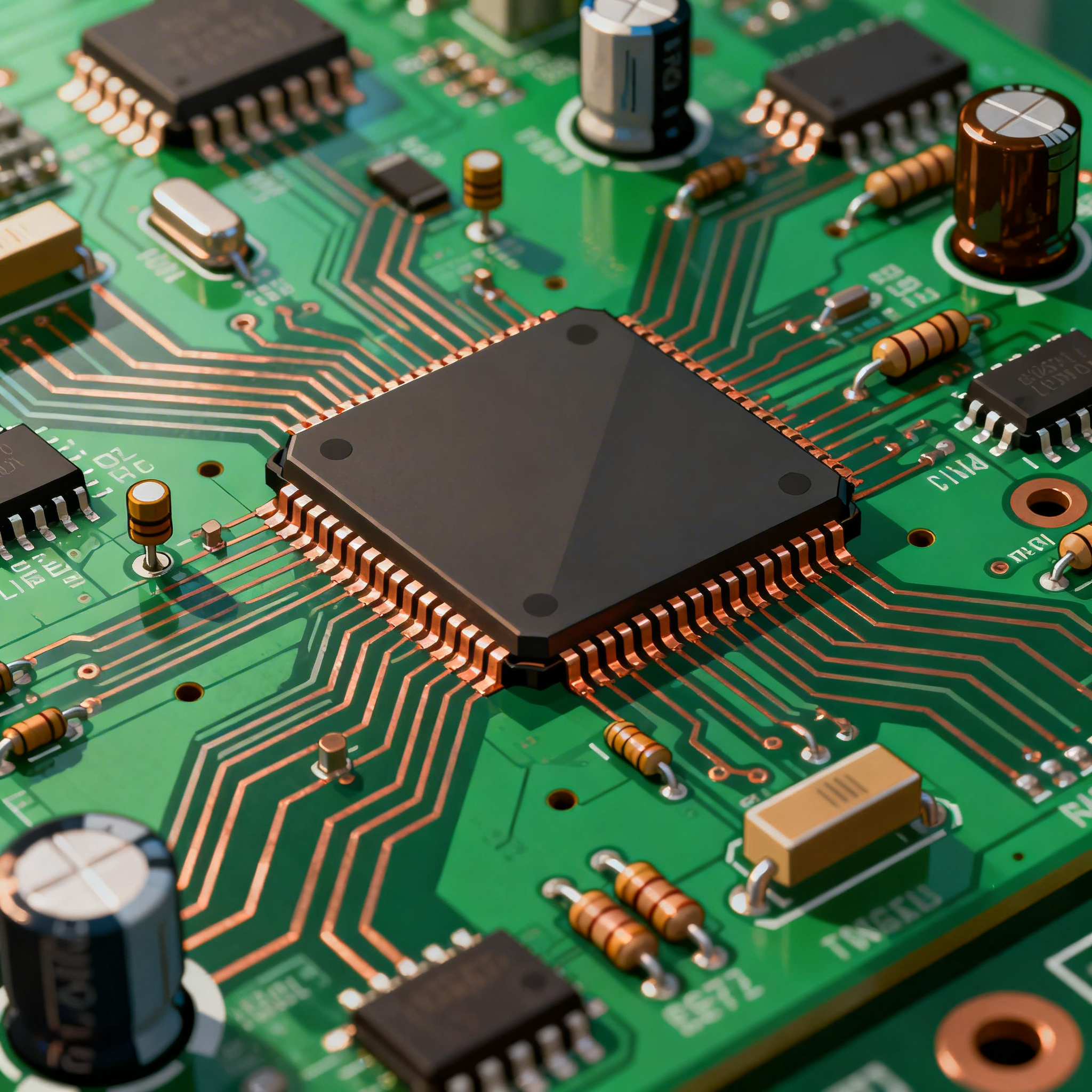
Printed Circuit Boards (PCBs) are the backbone of modern electronic devices, serving as the platform that connects various components. The architecture of a PCB includes multiple layers, each serving a specific purpose, such as power distribution, signal routing, and grounding. Key principles of PCB design involve optimizing the layout for performance, reliability, and manufacturability. Understanding the core concepts of PCB assembly, including soldering techniques, component placement, and thermal management, is essential for reducing costs and improving efficiency. Adhering to industry standards, such as IPC-A-610 and IPC-2221, ensures quality and consistency in PCB manufacturing.
Detailed Specifications
When selecting components for PCB assembly, understanding the core specifications is crucial. These specifications determine the functionality and performance of the final product. Key parameters include CPU speed, memory capacity, peripheral interfaces, power requirements, and packaging options. Analyzing these specifications helps in choosing the right components that meet both technical and budgetary constraints.
| Specification | Parameter | Description |
|---|---|---|
| CPU Speed | 1.2 GHz | Processor speed impacting overall performance |
| Memory | 256 MB | Volatile storage for processing tasks |
| Peripheral Interfaces | USB, I2C, SPI | Connectivity options for external devices |
| Power Supply | 3.3V | Voltage required for operation |
| Package Type | LQFP | Low-profile quad flat package for compact designs |
| Operating Temperature | -40°C to 85°C | Suitable for harsh environments |
| Clock Speed | 100 MHz | Rate at which a processor executes instructions |
| ROM | 512 KB | Non-volatile storage for firmware |
| ADC Channels | 8 | Analog-to-digital conversion capacity |
| GPIO Pins | 32 | General-purpose input/output for flexibility |
| Package Size | 7x7 mm | Physical dimensions of the component |
Key Takeaways from the Specifications
The core specifications of a component significantly influence its suitability for a given application. For instance, a CPU speed of 1.2 GHz and memory of 256 MB are ideal for moderate computing tasks, while the availability of interfaces like USB, I2C, and SPI provides flexibility in connecting to various peripherals. The power supply requirement of 3.3V suggests a low-power design, crucial for battery-operated devices. Understanding these parameters helps in choosing components that not only meet the technical requirements but also align with cost and space constraints, ultimately enhancing the efficiency of PCB assembly.
| Characteristic | Value | Implication |
|---|---|---|
| Input Voltage | 1.8V - 3.6V | Wide voltage range for flexible power sources |
| Operating Current | 15 mA | Low current draw for energy efficiency |
| Output Current | 25 mA | Capability to drive external loads |
| Clock Frequency | 100 MHz | Determines processing speed |
| Input Capacitance | 5 pF | Low capacitance for fast signal response |
| Output Capacitance | 10 pF | Stability in output signals |
| Propagation Delay | 5 ns | Quick signal transmission |
| Rise Time | 2 ns | Fast signal rise for sharp transitions |
| Fall Time | 2 ns | Fast signal fall for sharp transitions |
| I/O Voltage Levels | TTL | Compatibility with standard logic levels |
| Thermal Resistance | 30°C/W | Effective heat dissipation |
Practical Implications
The electrical characteristics of a component are pivotal in determining its performance and integration within a PCB design. A wide input voltage range of 1.8V to 3.6V allows for versatility in power supply choices. The low operating current of 15 mA is beneficial for battery-powered applications, ensuring energy efficiency. Fast propagation delay and rise/fall times indicate a component's ability to handle high-speed data processing, making it suitable for time-sensitive applications. Understanding these characteristics aids in optimizing the design for performance and reliability while controlling costs.
| Use Case | Configuration | Benefits |
|---|---|---|
| Consumer Electronics | Integrated MCU with ADC | Cost-effective and compact design |
| Industrial Automation | High I/O count with robust ADC | Reliable performance in harsh conditions |
| Automotive Systems | Extended temperature range, CAN interface | Durability and connectivity |
| IoT Devices | Low power, wireless connectivity | Energy efficiency and remote operation |
| Medical Devices | Precision ADC, low noise | Accurate data acquisition |
| Telecommunications | High-speed processing, multiple interfaces | Efficient data handling |
| Home Automation | Wi-Fi/Bluetooth integration | Convenient and user-friendly |
Application Guidelines
The application comparison highlights how different configurations serve various industries. For instance, consumer electronics benefit from an integrated MCU with ADC for a cost-effective and compact design. In industrial automation, a high I/O count with a robust ADC ensures reliable performance in demanding environments. Automotive systems require components with extended temperature ranges and CAN interfaces for durability and connectivity. Understanding these configurations allows engineers to tailor designs to specific use cases, optimizing both functionality and cost-effectiveness.
Design Considerations
Practical design guidelines are essential for ensuring the success of PCB assembly while minimizing costs. Firstly, selecting components with a high level of integration can reduce the number of parts required, simplifying the assembly process and reducing costs. Secondly, designing for manufacturability involves considering the capabilities and limitations of the assembly process, such as component spacing and soldering techniques. Utilizing standardized components can also lead to cost savings by leveraging economies of scale. Additionally, thermal management is crucial in preventing overheating and ensuring long-term reliability. Implementing design rules, such as maintaining adequate trace widths and using thermal reliefs, helps manage heat dissipation effectively. Finally, thorough testing and validation at each stage of design can prevent costly rework and ensure a smooth transition from prototype to production.
Step-by-Step Implementation
Implementing a cost-effective PCB assembly process involves several detailed steps:
- Component Selection: Begin by identifying components that meet the technical requirements and budget constraints. Use component databases and manufacturers' datasheets to compare specifications and costs.
- Design for Manufacturability (DFM): Optimize the PCB layout for efficient assembly by considering factors such as component orientation, spacing, and thermal management. Utilize DFM guidelines to ensure compatibility with assembly processes.
- Prototype Development: Develop a prototype to validate the design. This step is crucial for identifying potential issues and making necessary adjustments before full-scale production.
- Testing and Validation: Conduct thorough testing to ensure the PCB meets all performance and reliability criteria. Use automated test equipment (ATE) for efficient and accurate testing.
- Supplier Engagement: Collaborate with suppliers to negotiate favorable terms and ensure timely delivery of components. Establish clear communication channels to address any supply chain issues promptly.
- Cost Analysis: Perform a detailed cost analysis to identify areas for potential savings. Consider factors such as component costs, assembly labor, and overhead expenses.
- Continuous Improvement: Implement a feedback loop to gather insights from the production process and make continuous improvements. Encourage cross-functional collaboration to identify innovative cost-reduction strategies.
Common Issues & Solutions
PCB assembly often encounters challenges that can impact cost and quality. Here are some common issues and their solutions:
- Component Shortages: Mitigate this by maintaining a buffer stock and diversifying suppliers to reduce dependency on a single source.
- Soldering Defects: Address soldering issues by optimizing reflow profiles and conducting regular equipment maintenance.
- Thermal Management: Implement heat sinks and thermal vias to manage heat dissipation effectively, preventing component failure.
- Signal Integrity Problems: Use proper grounding techniques and impedance matching to prevent signal degradation.
- Design Errors: Conduct thorough design reviews and simulations to catch errors early in the design phase.
- Quality Control: Establish stringent quality control measures and conduct regular audits to ensure consistent product quality.
Applications & Use Cases
PCB assemblies are integral to various industries, each with unique requirements. In consumer electronics, PCBs enable compact and efficient designs for smartphones and tablets. Industrial automation relies on robust PCBs for reliable performance in harsh environments. Automotive systems require PCBs that can withstand extreme temperatures and vibrations. The medical field uses precision PCBs for accurate data acquisition in diagnostic equipment. Telecommunications depend on high-speed PCBs for efficient data handling, while IoT devices benefit from low-power PCBs for remote operation. Understanding these applications allows engineers to tailor PCB designs to specific industry needs, ensuring optimal performance and cost-effectiveness.
Selection & Sourcing Guide
Selecting and sourcing components for PCB assembly requires careful consideration of technical specifications, cost, and availability. Utilize online resources such as IC Online to compare component specifications and prices across different suppliers. Establish relationships with reliable suppliers to ensure consistent quality and timely delivery. Consider factors such as minimum order quantities (MOQs) and lead times when sourcing components. By leveraging these strategies, engineers can optimize the selection and sourcing process, reducing costs and ensuring the success of PCB assembly projects.
FAQ
- What is the importance of component specifications in PCB assembly? Component specifications determine the performance, compatibility, and cost-effectiveness of the PCB, impacting the overall success of the project.
- How can I reduce PCB assembly costs? Strategies include selecting integrated components, optimizing design for manufacturability, and conducting thorough testing to prevent rework.
- What role does thermal management play in PCB design? Effective thermal management prevents overheating, ensuring long-term reliability and performance of the PCB.
- How do I choose the right components for my PCB? Consider technical specifications, cost, and availability. Use online resources and supplier catalogs to compare options.
- What are some common assembly defects? Common defects include soldering issues, component misalignment, and thermal management problems, all of which can be mitigated with proper design and process controls.
- How can I ensure quality in PCB assembly? Implement stringent quality control measures, conduct regular audits, and establish clear communication with suppliers to maintain consistent quality.
- What are the benefits of using standardized components? Standardized components reduce costs through economies of scale and simplify the assembly process, leading to faster production times.
- How do I manage component shortages? Maintain a buffer stock, diversify suppliers, and establish contingency plans to address potential supply chain disruptions.
- What is the significance of IPC standards in PCB manufacturing? IPC standards ensure quality, consistency, and reliability in PCB design and assembly, providing guidelines for best practices.
- How can I improve signal integrity in my PCB design? Use proper grounding techniques, impedance matching, and shielding to prevent signal degradation and ensure reliable performance.
Conclusion
Reducing the cost of PCB assembly while maintaining quality is a complex challenge that requires a strategic approach. By understanding component specifications, optimizing design for manufacturability, and implementing effective sourcing strategies, engineers can achieve cost-effective and reliable PCB assemblies. Emphasizing quality control and continuous improvement further enhances the success of PCB projects. With the right strategies in place, manufacturers can meet the growing demand for efficient and cost-effective electronic solutions.